
Why Synthetic Pitch Drainage Demands an Engineering Overhaul
Modern synthetic sports pitches are expected to remain safe, playable and visually consistent through increasingly intense rainfall. That expectation is difficult to meet when drainage is treated as a finishing detail rather than as part of the structural design. Short, high-intensity storms can exceed the infiltration capacity of compacted subgrades, while repeated wetting and drying can weaken interfaces, create settlement and move infill or carpet layers. Facilities with tight booking schedules are particularly exposed because even a short period of waterlogging can lead to cancelled fixtures, restricted training and expensive remedial work.
Regulatory pressure reinforces the operational case. In England, the national SuDS standards promote management close to source, controlled flows, water-quality treatment and, where practicable, infiltration or reuse before discharge to surface-water or combined sewers. Similar principles apply across the UK through local planning and drainage authorities. Traditional dense aggregate layers can work well as load-bearing platforms, but their fine content may restrict vertical flow and allow perched water to form beneath the pitch. The more resilient approach combines an open-graded structural sub-base, a properly selected filtration membrane and verified storage with a controlled outlet.
Decoding Aggregates Type 3 Open-Graded Versus Standard Type 1
MOT Type 1 is widely used because it grades tightly, compacts into a stable mass and distributes traffic loads effectively. Its particle range commonly includes crushed stone from approximately 40 mm down to dust. That fine fraction fills the voids between larger particles, which is useful when a relatively impermeable, tightly bound platform is required. It is less suitable as the principal drainage layer beneath a synthetic pitch, particularly where rainfall must pass quickly through the construction build-up. Fines can reduce hydraulic conductivity during installation, and mobile silt from the subgrade can make the problem progressively worse.
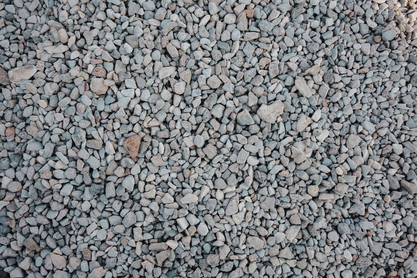
DoT Type 3, by contrast, is a reduced-fines, open-graded aggregate typically formed from clean crushed stone in the 4 to 40 mm range. The larger interconnected voids provide routes for water to move laterally and vertically while retaining substantial temporary storage. The material still offers angular particle contact and load distribution, but it should not be judged by the same compaction expectations as Type 1. Excessive rolling or vibration can crush particles, generate fines and undermine the very void structure the design depends on. The selected grading, layer depth, underlying soil and expected loading must therefore be checked together.
| Design factor | Type 1 aggregate | Type 3 open-graded aggregate |
|---|---|---|
| Particle distribution | Broad range including significant fines | Reduced fines with larger interconnected particles |
| Primary performance | Dense, stable load-bearing platform | Load support combined with rapid drainage |
| Void structure | Low after tight compaction | Higher, subject to clean material and controlled installation |
| Water movement | Restricted, particularly as fines migrate | More continuous flow paths and storage capacity |
| Main risk | Clogging and perched water | Segregation, settlement or particle crushing if mishandled |
Material selection should focus on a clean, durable crushed-stone blend with a documented grading curve, not simply on a product name. The aggregate must be compatible with the geotextile above and below it, and the source should be checked for contamination, excessive dust and weak particles. During procurement, require delivery tickets, grading information and a clear method statement for placement. When sizing permeable foundations, engineers often evaluate advanced drainage cells alongside open-graded aggregates to maintain peak hydraulic void capacity. This combined approach is useful where the pitch footprint is constrained or where the calculated storm volume cannot be held safely in stone alone.
Geotextile Membranes and Separation Layer Architecture
Even a well-designed open-graded base can fail if it becomes contaminated. Fine particles from clay, silty subgrade or construction traffic can migrate upward under water movement and loading, gradually filling the aggregate voids. This process, often described as blinding or clogging, reduces both permeability and storage. A geotextile separation layer limits intermixing while allowing water to pass. It must be selected for the actual soil grading, hydraulic demand, tensile loading, puncture exposure and installation conditions, rather than specified as a generic membrane.
Non-woven needle-punched geotextiles are commonly used where conformability, filtration and high water flow are important. Their three-dimensional fibre structure can accommodate uneven ground and retain fine particles while transmitting water. Woven products generally provide higher tensile strength and lower elongation, but their filtration behaviour depends strongly on the weave and apparent opening size, or AOS. The design should compare AOS with the subgrade particle distribution and verify normal-to-plane flow under the expected head. The membrane architecture should extend from the prepared subgrade through the aggregate interfaces and, where used, around cellular drainage layers.
- Trim and proof-roll the subgrade before membrane placement, removing sharp stones and construction debris.
- Lay the geotextile smoothly without folds, bridging or overstretched areas.
- Use specified laps or thermally bonded seams, with wider overlaps where the ground is soft or installation conditions are difficult.
- Pin only where necessary, using fixings that do not create concentrated tear points beneath trafficking routes.
- Protect exposed membrane from prolonged ultraviolet exposure and uncontrolled plant movement.
- Turn the membrane into perimeter drainage details and secure edge terminations against washout.
The usual sequence is a prepared formation, subgrade separation geotextile, open-graded structural stone, any secondary filter or regulating layer, drainage grid or collector system, shock pad and synthetic carpet. The precise build-up depends on the sport, performance standard and drainage strategy. Guidance on statutory water management standards published by national authorities highlights the importance of construction quality, maintenance access and reliable treatment pathways. For a pitch, that means preventing sediment blind spots before they become inaccessible defects.
Sizing Geocellular Attenuation and Dynamic Storage Layers
Attenuation design begins with a site-specific rainfall model, not a standard cell depth. The calculation should identify the contributing impermeable and permeable areas, design storm duration, critical rainfall intensity, existing runoff characteristics and the permitted discharge rate. The model must include the required return period, commonly the 1-in-100-year event for major drainage design, together with the applicable climate-change allowance set by the approving authority. The result is a maximum storage requirement and a discharge hydrograph, not merely a volume estimate.
Storage can be provided within the open-graded stone, in shallow micro-honeycomb grids, in deeper geocellular tanks outside the playing area, or through a combination of these layers. A 60 mm drainage grid, for example, can create a continuous drainage plane beneath artificial turf and help move water toward collectors while preserving a shallow construction profile. Deeper systems provide greater void volume where land is limited, but require careful structural design, inspection access and protection from loading. Product selection must account for compressive performance, installation depth, groundwater, maintenance access and whether the system is intended for infiltration, attenuation or both.
Natural disposal should be confirmed through field testing. BRE Digest 365 infiltration testing is commonly used to assess whether the ground can accept the calculated flow, with test locations and depths chosen to represent the proposed infiltration zone. Testing should consider seasonal groundwater and soil variability, since a single favourable result may not represent the whole pitch footprint. Where infiltration is unsuitable, the design should route stored water to an approved surface-water connection or other lawful outfall.
- Establish the design rainfall event and climate allowance required by the drainage authority.
- Calculate runoff from the full pitch, perimeter hardstanding, roofs and ancillary areas that discharge into the system.
- Determine available void volume using the tested porosity of stone and the manufacturer”s net storage data for cellular systems.
- Apply appropriate factors for sedimentation, construction tolerance, blocked inlets and long-term performance.
- Size flow-control chambers, throttles or hydro-brakes to meet the permissible discharge, often linked to greenfield runoff or an agreed restricted rate.
- Provide access for inspection, jetting and maintenance, and record the system in the facility”s drainage management plan.
SuDS should also be considered as part of the wider site rather than as an isolated tank beneath the carpet. The UK government framework encourages runoff to be treated as a resource and managed according to a hierarchy that prioritises reuse and infiltration where practicable. On larger sites, swales, filter trenches, detention features or planted treatment areas can reduce the burden on below-ground storage and improve water quality. The pitch drainage design must still protect the playing surface from surcharge, backflow and differential settlement.
Step-by-Step Installation Protocol for Contractor Teams
Construction tolerances determine whether the drainage model survives contact with the site. The first stage is formation preparation. Excavate to the designed depth, remove soft spots and establish a consistent fall toward collectors or drainage outlets. Laser grading is preferable for controlling levels across a large pitch, but it should be supported by regular survey checks. Proof-rolling and plate bearing verification should confirm that the formation can support the planned build-up without rutting or pumping. Weak areas should be undercut and replaced with approved material rather than concealed beneath the membrane.
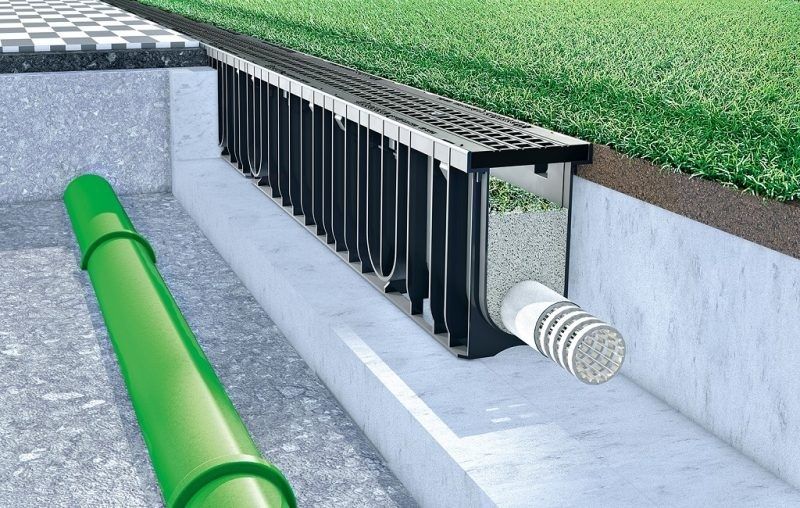
The second stage is membrane and collector installation. Deploy the separation geotextile across the formation, maintaining the specified laps and carefully detailing corners, channels and perimeter edges. Install lateral collectors, carrier pipes and inspection chambers to the surveyed falls. Connections should be tested before covering, and pipe surround material should be compatible with the filtration strategy. No construction plant should traffic directly over unprotected membrane where it could stretch, puncture or drag the fabric out of position.
The third stage is placement of the open-graded stone. Deliver aggregate as close as practical to its final position, then spread in controlled lifts using low-ground-pressure equipment. Avoid dumping large stockpiles onto unsupported membrane or driving repeatedly over finished areas. Compaction should seat the particles and remove unstable high points without crushing the aggregate. The completed layer should be surveyed for thickness, level, crossfall and local depressions before the upper drainage system is installed.
- Form and verify the subgrade, including levels, bearing capacity, soft-spot treatment and drainage falls.
- Deploy the geotextile, install collectors and complete inspection points, edge returns and outlet connections.
- Place clean open-graded stone in controlled lifts, using measured compaction that preserves the designed void structure.
- Install the drainage grid, secondary membranes, shock absorption pad and any regulating or protection layers.
- Lay and seam the synthetic turf carpet, secure perimeter restraints and complete infill installation in accordance with the sports system specification.
- Test outlets, inspect levels and retain as-built records, material certificates, photographs and maintenance instructions.
The final stage requires close coordination between civil, drainage and turf teams. Products such as micro-honeycomb drainage grids may be laid in large sheets, but joints, cut edges and interfaces must follow the manufacturer”s installation details. The surface should not be accepted solely on appearance. Water testing, outlet checks, level surveys and inspection of collector access points provide stronger evidence that the completed pitch will perform under storm conditions. Clear handover information is equally important, because blocked outlets or damaged edge details can eventually defeat a sound sub-base.
Deliver Long-Lasting Playing Surfaces Through Precise SuDS Design
A resilient synthetic pitch depends on three linked controls. Open grading creates the hydraulic capacity and temporary void storage needed beneath the playing surface. Correctly engineered geotextiles prevent subgrade fines from migrating into those flow paths. Geocellular or other attenuation layers provide verified storage when rainfall exceeds immediate infiltration or discharge capacity. Each element must be designed as part of one system, with the aggregate, membrane, collector network, outlet and maintenance plan working together.
For facility managers and contractors preparing future tenders, the immediate priority is to specify performance rather than rely on familiar material labels. Require site investigation, infiltration testing where relevant, stormwater modelling, climate allowances, grading certificates, membrane properties, installation tolerances and commissioning tests. Ask for accessible maintenance points and a documented inspection schedule. These controls reduce rain-related cancellations, protect the carpet and shock pad from prolonged saturation, limit corrective excavation and support planning compliance. In practical terms, careful drainage engineering converts the pitch from a vulnerable surface into a dependable asset that remains available when the weather is least predictable.